what
is is ospf inter area
In OSPF
(Open Shortest Path First), an inter-area
route refers to a route that crosses an Area Border Router (ABR) and
moves between different OSPF areas. Let me explain further:
·
Intra-Area
Routes (Type 1 LSA): These routes are
entirely within a single OSPF area. They are generated by OSPF routers within
the same area and are used for communication within that area. In the routing
table, intra-area routes are identified as O (e.g., O IA).
·
Inter-Area
Routes (Type 3 LSA): When a route
crosses an ABR (which connects different OSPF areas), it becomes an inter-area
route. These routes are advertised from one OSPF area to another. In the
routing table, inter-area routes are also flagged as O IA.
To summarize, both intra-area and
inter-area routes are considered OSPF
internal routes because they are generated by OSPF itself
based on the network configuration. If you’d like more details or have any
other questions, feel free to ask!
- Router LSA (Type 1):
- The Router LSA (Type 1) is
fundamental in OSPF. Each router within an OSPF area generates a Type 1
LSA for that area.
- What does it contain?
- Information about
the router itself, including:
- Router ID: The unique identifier for the router.
- Router interfaces: A list of all interfaces directly connected
to the router within the area.
- Neighbors: Details about neighboring routers.
- IP addresses: The IP addresses associated with each
interface.
- Cost: The cost (metric) associated with each link.
- How does it work?
- The Router LSA
remains confined within the area where it originated.
- It provides a
snapshot of the router’s local topology.
- Fun fact: Think of the Router
LSAs as puzzle pieces—each router contributes one, and together, they
form the complete picture of the OSPF link-state database (LSDB). 🧩
- Network LSA (Type 2):
- The Network LSA (Type 2) is
generated by the Designated Router (DR) in multi-access networks (such as
Ethernet LANs).
- What’s inside?
- A list of routers
connected to the multi-access network.
- The DR’s IP address.
- The network prefix
and subnet mask.
- Remember: Broadcast and
non-broadcast network types require a DR/BDR (Backup Designated Router).
If a DR exists, it generates the Network LSAs.
- Like the Router LSA, the Network
LSA remains within the area where it was created.
- Summary LSA (Type 3):
- OSPF operates across multiple
areas, and we want full connectivity between them.
- When a router in one area (let’s
call it Area 1) learns about networks in another area (say, Area 2), it
creates a Type 3 summary LSA.
- This LSA is then flooded into
Area 0 (the backbone area) and subsequently into all other areas.
- Contrary to its name, the
“summary” LSA doesn’t inherently summarize anything—it simply informs
routers in other areas about prefixes from different areas.
- If you see entries labeled O
IA in the routing table, those are inter-area prefixes
represented by Type 3 summary LSAs.
Remember, the LSAs work together like puzzle pieces, revealing the intricate map of OSPF connectivity.
1-Configure fortigate to Internet
2-Configure lan to internet in fortigate
3-Configure VLAN with Cisco switch
Configure Fortigate 1 (FA-A0)
In Fortigate FA-A0 has to Area Area0 and Area 1
Configure Port4 as Management and Internet
Port1 As Area 0, IP Address:
10.10.10.0/24
Port2 As Area 1, IP Address:
1.1.1.0/24
Port3 As Area 1, IP Address:
2.2.2.0/24
Step1: We go to Port4 to configure as management port,
Please check first lesion
This
lesion we show only configure OSPF Multiple Area that we have 3 Area include
Area 0, Area 1, Area2.
Now we stand for Fotigate FA-A0
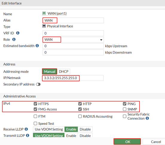
We enter Port1 to set IP Address via Management Port4
Network ðInterface click on Port1 chose button Edit it show new dialog box please fill in. This example we show you as diagram above
Now we set IP Address on Port1 done,
Enter Port2 set As Area 1 IP address 1.1.1.1/24
Network Interface select Port2 chose
Dialog box Edit
Now we set IP Address on Port2 done,
Enter Port3 set As Area 1 IP address 2.2.2.1/24
Network Interface select Port3 chose
Dialog box Edit
Now we finished set IP address in Fortigate FT-A0
We enter Fortgate2 (FT-A1)
In Fortigate FA-A1 has only Area1
Port4 as Management, IP Address: 192.168.37.13/24
Port1 as Area 1, IP Address: 1.1.1.2/24
Port2 as Area 1, IP Address: 192.168.10.1/24
Step1: We go to Port4 to configure as management port,
Please check first lesion
Enter
port1 to set IP address 1.1.1.2/24
Network Interface select Port1 click
dialog box Edit
Set IP address on Port1 done
Enter Port2 to set IP address for LAN10: 192.168.10.1/24
Network Interface select Port2 click
dialog box Edit
Finish set IP address in Port2
Configure Fotigate3 (FTA1-1)
In
Fortigate FA-A1-1 has only Area1
Configure Port4 as Management Port
IP Address: 192.168.37.14/24
Port1
as Area 1, IP address: 2.2.2.2/24
Port2
as Area 1, IP address: 192.168.20.1/24
Log to fortigate via Management
port4 https://192.168.37.14
Enter
port1 set IP Address 2.2.2.2/24
Network Interface select Port1 click on Edit dialog box
Set IP Address in Port1 done
Enter port2 to set IP Address: 192.168.20.1/24
Network Interface select Port2 click on Edit dialog box
Finished in set ip address in Port2
To set OSPS Routing Protocol Fortigate (FTA1-1)
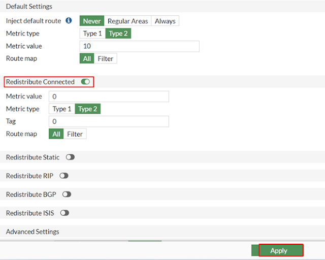
Network OSPF
Router
ID: 2.2.2.2 (This lap we get ip as router ID)
Area ID:
0.0.0.1
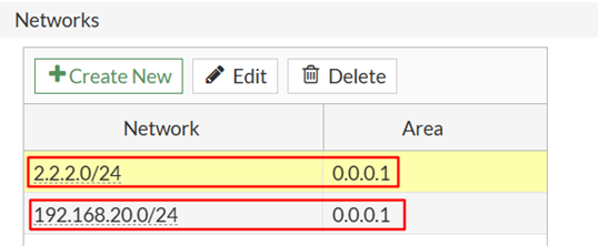
Network
2.2.2.0/24
Networks
192.168.20.0/24
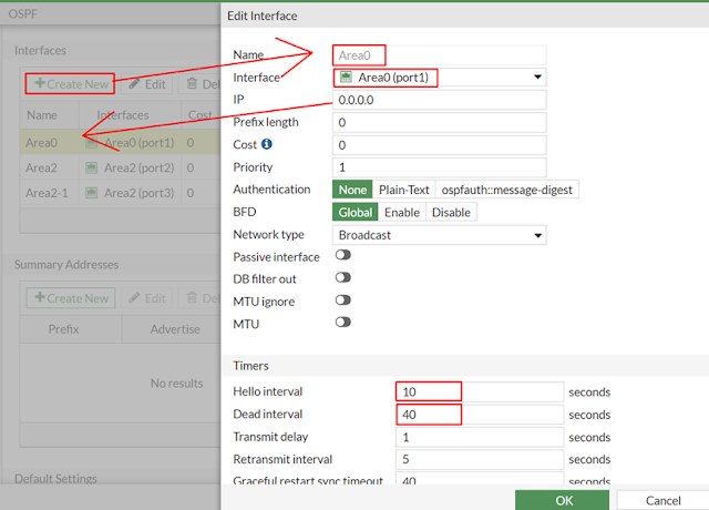
Interface
Name:
Area1 Interface: WAN
Name:LAN20
Interface: LAN20
Configure Policy & Objects
Policy
& Object Firewall Policy it show
new dialog box Create new
Allow WAN access to LAN
Allow LAN access to Internet
Configure OSPF Forigate 1 (FT-A0)
Network ðOSPF
it show dialog box click Create New
Router
ID 10.10.10.2 (This lap we use IP Address as Router ID)
Area ID:
Area 0: 0.0.0.0
Area
1: 0.0.0.1
Network
10.10.10.0/24
1.1.1.0/24
2.2.2.0/24
Interface
Name
Area 0 to Interface Port1
Name
Area1 to Interface Port2
Name
Area 2 to Interface Port3
Finished configure OSPF in Fortigate (FT-A0), To check whether working or not we can check in Daskboard or
Using Command link
To check on Dashboard and select Network at
the top left conner dropdown list chose OSPF Neighbors
Configure Policy & Object
Configure
Area 1 to Internet enter Policy & Object and select Firewall
Policy
Configure Area 1 talk each other
Reverse
Allow Area1 can access to Area2 via Area0
Reverse Allow Area2
can access to Area1 via Area0
Result
Configure OSFP Fortigate 3
(FT-A1-1)
Network
select OSPF it show new dialog box
Router ID: 2.2.2.2
Area 1: 0.0.0.1
Networks
Network
2.2.2.0/24 Area1: 0.0.0.1
Network
192.168.20.0/24 Area1: 0.0.01
Interface
Name
Area1 Interface WAN (Port1)
Name
LAN20 Interface
LAN20 (Port2)
Finished OSPF
Now we enter to configure Policy & Object
Policy
& Objects select Firewall Policy it show new dialog box Create
New it rule for WAN access to LAN
LAN access to WAN
Result
Finished in to Configure Policy & Object
Configure
Fortigate 5 (FT-A0-1)
This environment Configure Port4 as management port IP
address 192.168.37.12/24
Port1
as Area0 IP Address 10.10.10.3/24
Port2
as Area1 IP Address 3.3.3.1/24
Port3
as Area1 IP Address 4.4.4.1/24
Login to
fortigate to set ip address via https: 192.168.37.12
Network
select Interface it show new dialog box select port1 click
on dialog box Edit
Port2
Configure OSPF
Network select
OSPF click on Create New
Router ID: 10.10.10.3 (The
environment wet get IP address as router ID)
Area 0.0.0.0, 0.0.0.2
Networks
10.10.100/24
3.3.3.0/24
4.4.4.0/24
Interfaces
Name Area0 to Interface Port1
Name Area2 to Interface Port2
Name Area2 to Interface Port3
Configure Policy & Object
Policy
& Object select Firewall Policy it show new dialog box Create
New Allow Area2 to internet
Allow internet access to Area 2
Allow Area2 access to Area2
Reverse
Allow Area2 access to Area1
Reverse
Configure Fortigate 5 (FT-A2)
In Fortigate FA-A2 has only Area Area2
Configure Port4 as Management and Internet IP Address:
192.168.37.15/24
Port1 As Area 2, IP Address:
3.3.3.2/24
Port2 As Area 2, IP Address: 192.168.30.0/24
Set ip address
Network select Interface chose port1 click on dialog box Edit
Port2 LAN30
Configure OSPF
Network select OSPF click on Create New
Router
ID: 3.3.3.2 (This environment we get ip address as Router ID)
Area
2: 0.0.0.2
Networks
Network
3.3.3.0/24 Area: 0.0.02
Network
192.168.30.0/24 Area: 0.0.02
Interface
Name
Area2 Interface wan(port1)
Name
Area2 Interface LAN30(port2)
Configure Policy & Object
Allow
Lan to Internet
Policy
& Object select Firewall Policy click Create New
Allow Wan to LAN
Configure Fortigate 6 (FT-A2-1)
In Fortigate FA-A2 has only Area Area2
Configure Port4 as Management and Internet IP Address:
192.168.37.16/24
Port1 As Area 2, IP Address:
4.4.4.2/24
Port2 As Area 2, IP Address:
192.168.40.0/24
Set ip address
Network select Interface chose port1 click on dialog box Edit
Port2 LAN40
Configure OSPF
Network
select OSPF click Create New
Router
ID: 4.4.4.2 (This environment we get ip address as router id)
Area ID:
0.0.0.2
Networks
Network
4.4.4.0/24 Area2
0.0.0.2
Network
192.168.40.0/24 Area2 0.0.0.2
Interfaces
Name
Area2 Interface
Area2(port1)
Name
LAN40 Interface
LAN(port2)
Configure Policy & Object
Allow
LAN to Internet
Policy
& Object select Firewall Policy chose
Allow WAN to LAN
Now we testing Area1 to Area1
Test Area1 to Area2


